
11 single-pronged wires

1 MiCS-2710 NOx sensor

8 double pronged wires
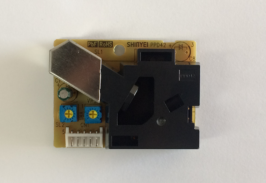
1 Shinyei PPD42 sensor

3 resistors
(2200 Ω, 100 Ω, and 27 Ω)
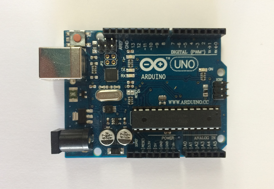
1 Arduino Uno/Genuino board

1 breadboard
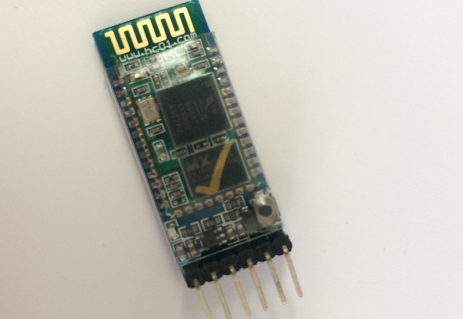
1 HC-05 bluetooth module
*Note: The MiCS-2710 sensor is no longer being produced and has been replaced by the MiCS-2714. The MiCS-2714 requires the same circuit and code as the MiCS-2710, but rather than plugging in wires it requires soldering directly to the sensor. This can be challenging, as it is easy to overheat the sensor destroying it. Instructions on the following pages can be used to build a device that includes both the NOx and PM sensors, or only the PM sensor.
Instructions:
1. Powering the positive rails

2. Grounding the negative rails

3. Heating the circuit for NOx
(*skip to step 5 for building PM sensor only)

4. Putting together the NOx detection circuit
(*skip to step 5 for building PM sensor only)

5. PM sensor circuit

6. Connecting the bluetooth module

If you are unfamiliar with using an Arduino, click here to become familiar with their structure.
3.3V and 5V refer to different voltages (different strengths of the electric flow). The power originates from the Arduino and is being transferred to the breadboard.
The positive rails are the column of pins alongside the red line. By powering one of these pins with a particular voltage, all the other pins in the positive rail become powered with that voltage.
Note: the way the pins are numbered may be misleading, but often there is a small 5 next to the pins to indicate which way the pins are numbered. To follow this diagram correctly, ensure that the green side of your PM sensor is facing up when you plug the three wires into the pins.
Also, cover the large hole of the PM sensor with paper or tape, but do not cover any other holes. View the photo below.

The completed circuit
